Plastic Part Design for Injection Molding
Three Critical Transitions to Optimize Your Part
When optimizing plastic part design for injection molding, we want to focus on how mold design affects part design. This proves important during that critical transition into injection molding. The high-risk transition brings unexpected frustrations that cause expensive delays when not following proper plastic part design for injection molding.
Risks during plastic part design for injection molding increase when clients rely upon multiple suppliers to manage various program phases. This means multiple companies must work together to effectively communicate and mitigate those risks. Otherwise, the team can leave major risks unidentified with no mitigation plan.
Many clients expect a new molded part will automatically match prototypes. They assume they can skip past the plastic part design for injection molding stage. Experience has proven this to be untrue because reality inevitably creeps back. To help reduce those hassles and unnecessary risks, we have specified three types of transitions during the development-to-manufacture transfer phase.
Transition 1 – From Rapid Prototypes to Injection Molded Parts
This transition starts during the early design and prototype phase. Rapid prototypes could include everything from 3D-printed parts to machined parts. Plastic part design for injection molding creates that bridge across completely different manufacturing processes.
Each production process introduces its own constraints and thus its own part design requirements. Unlike plastic part design for injection molding, design for 3D printing requires support structures. These support structures leave marks on the part when removed. Machined parts might need to be split so that inner features can be formed. You can read about designing for manufacture while transitioning from machining to injection molding here.
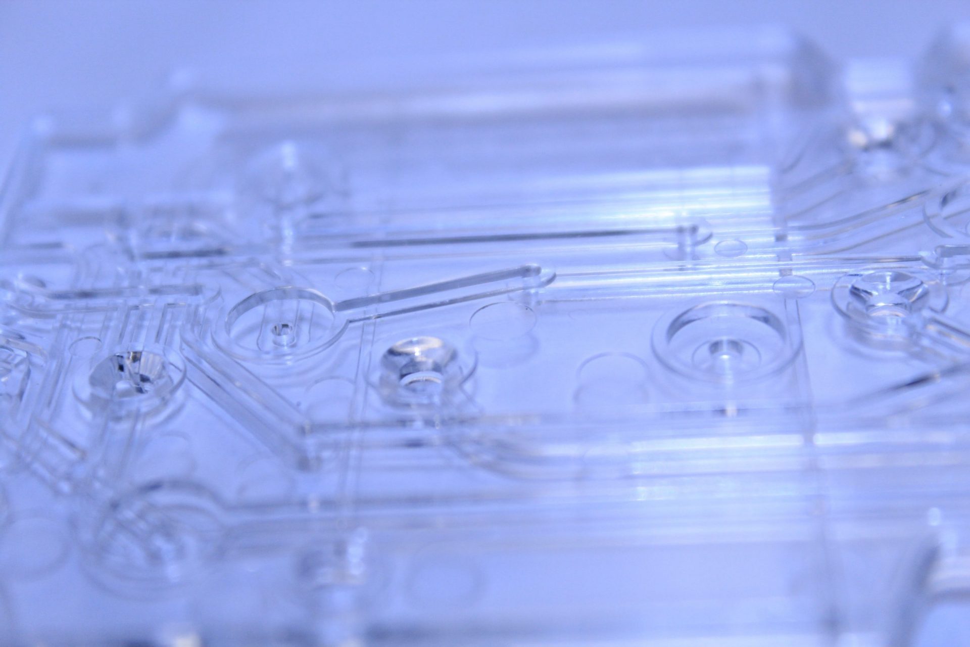
Plastic part design for injection molding brings its own constraints. Molded parts form by injecting hot resin into a core and cavity between two plates of steel. This means the part will have a parting line where the two plates of steel meet. Can you find the parting line in the female luer below?
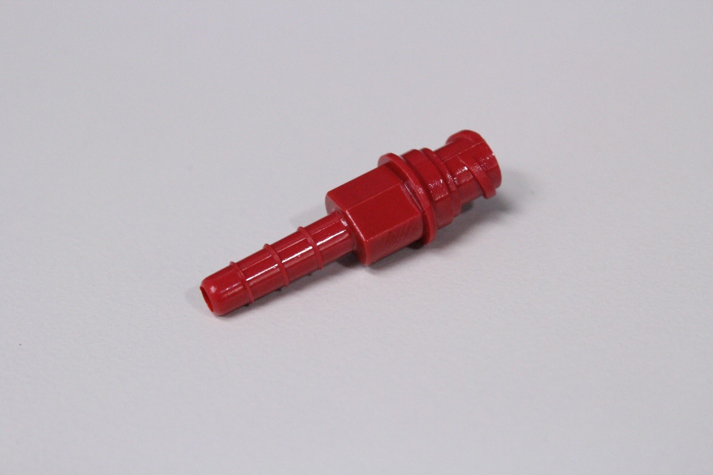
Plastic part design for injection molding also introduces a gate vestige where the resin enters the core and cavity. Where that gate vestige appears on the part might impact quality. Can you find the gate vestige on this male luer in the below image?
Transition 2 – From Rapid Molds to Single-Cavity Production Molds
This transition might make itself least apparent to some development teams. Why would we consider plastic part design for injection molding when we already have injection molded parts? After all, the transition from a single-cavity mold to a single-cavity mold does not seem impactful. However, this transition can catch development teams by surprise and introduce unfortunate delays.
Teams skip plastic part design for injection molding without realizing the impact of moving from rapid mold to production mold. Rapid molds might rely upon a person to remove each part manually. The mold might have no cooling channels and long cycle times.
Plastic part design for injection molding creates a production mold with a more automated process and faster cycle times. The production mold aims for efficiency and low maintenance. It produces higher quantities with a greater reliance on a consistent process to achieve quality.
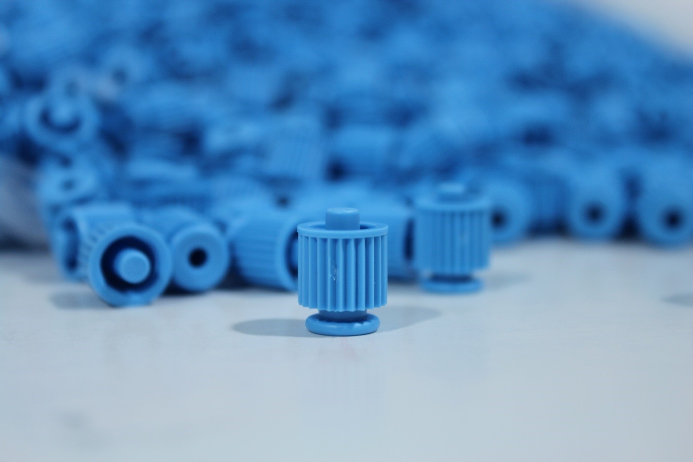
During this transition, plastic part design for injection molding also includes ejection. The mold includes ejector pins that automatically push the part out. This efficiency comes with a tradeoff. The introduction of these ejection pins creates ejector marks on the part. The location, size, and quantity of the marks can generate hot debates between part designers and mold designers. Can you find the ejector marks in the part below?
These debates during plastic part design for injection molding can grow painful but serve a greater purpose. The bigger threat arises when these debates do not happen. The program misses the collective wisdom of the team which can only be accessed through open discussion and productive debate.
Transition 3 – From Single-Cavity Molds to Multi-Cavity Molds
This transition introduces greater efficiency and even catches veterans by surprise. Once we had a CEO was transitioning from single-cavity to 16-cavity molds. We explained the need to adjust the plastic part design for injection molding on the high cavitation molds. He responded: “Can’t you just do the same thing 16 times?” We compared the task to transitioning from a single-story to a 16-story building. The complexity increases. You can read more about the important factors of proper mold design here.
The plastic part design for injection molding on a multi-cavity mold depends upon achieving that balanced fill. Much of this risk is best addressed during mold design. A thorough mold flow analysis by an experienced process engineer provides outputs that impact both part design and mold design.
Many unfortunate teams fail to address these common risks. They either fall into the trap of assuming the best-case scenario or fail to communicate those risks early enough. The good news is that you can manage those known risks by understanding plastic part design for injection molding.
Over time, Natech Engineers have accumulated a body of knowledge around plastic part design for injection molding. This helps predict what surprises will crop up and how to deal with them. By categorizing transition types, we can manage known risks to optimize plastic part designs for the injection molding process.
Speak directly to a Natech Engineer about plastic part design for injection molding. Our Engineers will let you know how plastic part design for injection molding applies to your project.